Cisco 2600 Series Cabling and Setup

1


1


Installing a Network Module
Use this procedure, if required, to install any network module in a Cisco 2600 series router.
Look for a network module in the slot labeled 1 on the left-rear of the router. If there is a network module already installed, connect the module to your network using the appropriate cable.
If you need to install a network module, follow this procedure:
1  Use a number 2 Phillips screwdriver to remove the screws that hold the metal plate over the network module slot cover and remove the metal covering plate.
For information on connecting network modules, refer to the Cisco Network Modules Hardware Installation Guideincluded in your router package.

Installing a WAN
Interface Card
Use this procedure, if required, to install any WAN interface card in a Cisco 2600 series router.
Look for a WAN interface card in the slots labeled W0 and W1 on the right-rear of the router. If there is a WAN interface card already installed, connect the card to the WAN line using the appropriate cable.
If you need to install a WAN interface card, follow this procedure:
1 Use a number 2 Phillips screwdriver to remove the screws that hold the metal plate over the card slot cover and remove the metal covering plate.
For information on connecting WAN interface cards, refer to the Cisco WAN Interface Cards Hardware Installation Guide included in your router package.

Connect the LAN Cable(s)
Position the router so you can reach the rear panel. The cables and the router's ports are color-coded to help you make the right connections.
Depending on the router model, connect your router to one or two LANs. Your LAN connection can be Ethernet, Fast Ethernet, Token Ring, or a combination. (See the hardware installation guide that accompanied your router for model configurations.)
Connect the Ethernet Cable(s)
1 Connect the yellow Ethernet cable to the yellow 10BaseT port labeled ETHERNET 0/0 on the rear panel of your router.

Connect the Fast Ethernet Cable(s)
1 Connect the yellow Ethernet cable to the
yellow 10/100BaseT port labeled
10/100 ETHERNET 0/0 on the rear panel of your router.
yellow 10/100BaseT port labeled
10/100 ETHERNET 0/0 on the rear panel of your router.

Connect the Token Ring Cable
1 Depending on the router model, connect the purple Token Ring cable to the RJ-45 port labeled TOKEN RING 0/0 on the rear panel of the router.
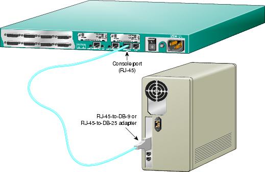
Connect the Console Cable
1 Connect the light-blue console cable to the light-blue port labeled CONSOLE on the rear panel of the router.
Use either the RJ-45-to-DB-9 adapter or the RJ-45-to-DB-25 adapter, depending on your local terminal or PC.

Note: The RJ-45-to-DB-25 adapter can be purchased from Cisco (Cisco part number 29-0810-01).

Connect Power and
Turn On the Router
1 Connect the black power cord to the power connector on the rear panel of the router.
The power LED on the front panel should be on. Your router is now operational.
You are now finished with physical installation of the router.
See the next section on using the initial configuration dialog (also called the setup script) in the System Configuration Dialog to configure your router.
You can configure your router manually using the setup script in the System Configuration Dialog. The setup script prompts you to enter values appropriate for your router and network. Many prompts include default answers, shown in square brackets following the question. Enter your response, or press Return to accept the default answer.
Note: You can request help at any time by entering a question mark (?) at a setup prompt. If you make a mistake, you can exit and run the System Configuration Dialog again. Press Ctrl-c, and type setup at the privileged EXEC mode (enable) prompt (2600#).
See the Software Configuration Guide (for Cisco 3600 series and Cisco 2600 series routers) for complete information on using the setup script to configure the router.
Step 1 Connect a console to your router. If you need help, see the "Connect the Console Cable" section.
Step 2 Power ON the router.
Messages will begin to appear in your terminal emulation program window.

Caution
Do not press any keys on the keyboard until the messages stop. Any keys pressed during this time are interpreted as the first command typed. It will take a few minutes for the messages to stop.
The beginnings of the messages look similar to the following.
Note: The messages vary, depending on the Cisco IOS software release and feature set you selected. The screen displays in this section are for reference only and might not exactly reflect the messages on your screen.
System Bootstrap, Version 11.3(1)XA, PLATFORM SPECIFIC RELEASED SOFTWARE (fc1)
Copyright (c) 1998 by cisco Systems, Inc.
C2600 platform with 32768 Kbytes of main memory
<Additional messages omitted.>
Step 3 When the following prompt appears, press Return to accept the default entry (yes) in square brackets:
Would you like to enter the initial configuration dialog? [yes]:
At any point you may enter a question mark?' for help.
Use ctrl-c to abort configuration dialog at any prompt.
Default settings are in square brackets '[]'.
Step 4 When the following prompt appears, press Return to see the current interface summary:
First, would you like to see the current interface summary? [yes]:
Any interface listed with OK? value "NO" does not have a valid configuration
Interface IP-Address OK? Method Status Protocol
Ethernet0/0 unassigned NO unset up up
Serial0/0 unassigned NO unset up down
Ethernet0/1 unassigned NO unset up up
Serial0/1 unassigned NO unset up down
Serial0/2 unassigned NO unset up down
Step 5 Enter a host name for the router (this example uses 2600):
Configuring global parameters:
Enter host name [Router]: 2600
The enable secret is a password used to protect access to privileged EXEC and
configuration modes. This password, after entered, becomes encrypted in the configuration.
Step 6 Enter an enable secret password. This password is encrypted (more secure) and cannot be seen when viewing the configuration:
Enter enable secret: xxxx
The enable password is used when there is no enable secret and when using older software
and some boot images.
Step 7 Enter an enable password that is different from the enable secret password. This password is notencrypted (less secure) and can be seen when viewing the configuration:
Enter enable password: guessme
The virtual terminal password is used to protect access to the router over a network
interface.
Step 8 Enter the virtual terminal password, which prevents unauthenticated access to the router through ports other than the console port:
Enter virtual terminal password: guessagain
Step 9 Respond to the following prompts as appropriate for your network:
Configure SNMP Network Management? [yes]:
Community string [public]:
Configure LAT? [no]:
Configure AppleTalk? [no]: yes
Multizone networks? [no]: yes
Configure DECnet? [no]:
Configure IP? [yes]:
Configure IGRP routing? [yes]:
Your IGRP autonomous system number [1]: 15
Note: If you answer no to IGRP, you will be prompted to configure RIP.
Configure CLNS? [no]:
Configure IPX? [no]: yes
Configure Vines? [no]:
Configure XNS? [no]:
Configure Apollo? [no]:
Configure bridging? [no]:
Step 10 From this point on in the setup script, the prompts you see vary depending on the interface modules in place in your router. Complete the setup steps for your router interface modules.
When you have completed the initial configuration dialog, messages appear describing the configuration command script.
Step 11 A setup script prompt asks if you want to save this configuration. If you answer no, the configuration information you entered is not saved, and you return to the Cisco 2600 router enable prompt (
2600#). Type setup to return to the System Configuration Dialog.
If you answer yes, the configuration is saved and you are returned to the router prompt (
2600>) (prompt depends on host name variable).Use this configuration? [yes/no]: yes
Building configuration...
Use the enabled mode 'configure' command to modify this configuration.
Press RETURN to get started!
%LINK-3-UPDOWN: Interface Ethernet0/0, changed state to up
%LINK-3-UPDOWN: Interface Ethernet0/1, changed state to up
%LINK-3-UPDOWN: Interface Serial0/0, changed state to up
%LINK-3-UPDOWN: Interface Serial0/1, changed state to down
%LINK-3-UPDOWN: Interface Serial0/2, changed state to down
%LINK-3-UPDOWN: Interface Serial1/0, changed state to up
%LINK-3-UPDOWN: Interface Serial1/1, changed state to down
%LINK-3-UPDOWN: Interface Serial1/2, changed state to down
<Additional messages omitted.>
Step 12 When the messages stop displaying on your screen, press Return to get the prompt (prompt depends on host name variable):
2600>
The
2600> prompt indicates that you are now at the command-line interface (CLI) and you have just completed a basic router configuration.
No comments:
Post a Comment