configuring cisco router

Cisco 2600 Series Cabling and Setup


1

Take Out What You Need


Cisco 2600 series router
Black power cable

Open Me First Pouch

Cisco 2600 Series Cabling and Setup quick start guide (this publication)
Software Configuration Guide (for Cisco 3600 series and Cisco 2600 series routers)
Light-blue console cable with an RJ-45 connector
Yellow Ethernet cable(s) 
(one or two, quantity depends on your router model)
Purple Token Ring cable (if required)
RJ-45-to-DB-9 serial connector (if required)

Take Out What You Need (continued)


1

Open If Needed Pouch

Black auxiliary port cable
Cisco 2600 Series Hardware Installation Guide
Cisco Network Modules Hardware Installation Guide
Cisco WAN Interface Cards Hardware Installation Guide
Regulatory Compliance and Safety Informationpublication
DB-25 modem connector
Rack-mount kit
Rubber feet set
Connector hardware kit

Install Modules


Installing a Network Module

Use this procedure, if required, to install any network module in a Cisco 2600 series router.
Look for a network module in the slot labeled 1 on the left-rear of the router. If there is a network module already installed, connect the module to your network using the appropriate cable.
If you need to install a network module, follow this procedure:
1 Use a number 2 Phillips screwdriver to remove the screws that hold the metal plate over the network module slot cover and remove the metal covering plate.
2 Hold the network module by the handle and line the module up with the guides on either side of the slot.
3 Push the module into place until the edge connector is securely seated in the connector on the motherboard. Ensure that each of the module's captive screws lines up with its hole in the chassis.
4 Use the number 2 Phillips screwdriver to secure the captive mounting screws into the holes of the chassis.
5 Connect the appropriate network module cable(s) to your network.
For information on connecting network modules, refer to the Cisco Network Modules Hardware Installation Guideincluded in your router package.

Install Modules (continued)


Installing a WAN 
Interface Card

Use this procedure, if required, to install any WAN interface card in a Cisco 2600 series router.
Look for a WAN interface card in the slots labeled W0 and W1 on the right-rear of the router. If there is a WAN interface card already installed, connect the card to the WAN line using the appropriate cable.
If you need to install a WAN interface card, follow this procedure:
1 Use a number 2 Phillips screwdriver to remove the screws that hold the metal plate over the card slot cover and remove the metal covering plate.
2 Hold the WAN interface card by the edges and line the card up with the guides on either side of the slot.
3 Insert the card in the slot and push in until it is firmly seated in the connector and the card's front panel is flush with the router's rear panel.
4 Use the number 2 Phillips screwdriver to tighten the captive screws that are in the card.
5 Connect the card to the WAN line using the appropriate cable(s).
For information on connecting WAN interface cards, refer to the Cisco WAN Interface Cards Hardware Installation Guide included in your router package.

Connect Cables


Connect the LAN Cable(s)

Position the router so you can reach the rear panel. The cables and the router's ports are color-coded to help you make the right connections.
Depending on the router model, connect your router to one or two LANs. Your LAN connection can be Ethernet, Fast Ethernet, Token Ring, or a combination. (See the hardware installation guide that accompanied your router for model configurations.)

Connect the Ethernet Cable(s)

1 Connect the yellow Ethernet cable to the yellow 10BaseT port labeled ETHERNET 0/0 on the rear panel of your router.
2 Connect the other end of the Ethernet cable to an Ethernet hub or switch (not supplied).
3 If your router model uses dual Ethernet LANs, repeat Step 1 and Step 2 for the second Ethernet LAN connection (ETHERNET 0/1).

Connect Cables (continued)


Connect the Fast Ethernet Cable(s)

1 Connect the yellow Ethernet cable to the 
yellow 10/100BaseT port labeled 
10/100 ETHERNET 0/0 on the rear panel of your router.
2 Connect the other end of the Ethernet cable to an Ethernet hub or switch (not supplied).
3 If your router model uses dual Fast Ethernet LANs, repeat Step 1 and Step 2 for the second Ethernet LAN connection
(10/100 ETHERNET 0/1).

Connect Cables (continued)


Connect the Token Ring Cable

1 Depending on the router model, connect the purple Token Ring cable to the RJ-45 port labeled TOKEN RING 0/0 on the rear panel of the router.
2 Connect the other end of the Token Ring cable to a switch such as the Cisco Catalyst 3900 (not included), or to your Token Ring network.

Connect Cables (continued)


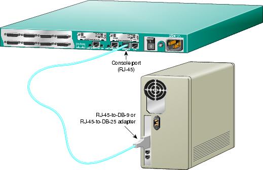
Connect the Console Cable

1 Connect the light-blue console cable to the light-blue port labeled CONSOLE on the rear panel of the router.
2 Connect the other end of the light-blue console cable to an RJ-45 adapter.
Use either the RJ-45-to-DB-9 adapter or the RJ-45-to-DB-25 adapter, depending on your local terminal or PC.

Note:   The RJ-45-to-DB-25 adapter can be purchased from Cisco (Cisco part number 29-0810-01).

3 Attach the adapter to a serial port on a terminal or PC running emulation software to allow router configuration.

Connect Cables (continued)


Connect Power and 
Turn On the Router

1 Connect the black power cord to the power connector on the rear panel of the router.
2 Connect the other end of the power cord to the electrical outlet.
3 Turn ON the router by pressing the ON/OFF switch on the rear panel.
The power LED on the front panel should be on. Your router is now operational.
You are now finished with physical installation of the router.
See the next section on using the initial configuration dialog (also called the setup script) in the System Configuration Dialog to configure your router.

Run Setup


You can configure your router manually using the setup script in the System Configuration Dialog. The setup script prompts you to enter values appropriate for your router and network. Many prompts include default answers, shown in square brackets following the question. Enter your response, or press Return to accept the default answer.

Note:   You can request help at any time by entering a question mark (?) at a setup prompt. If you make a mistake, you can exit and run the System Configuration Dialog again. Press Ctrl-c, and type setup at the privileged EXEC mode (enable) prompt (2600#).

See the Software Configuration Guide (for Cisco 3600 series and Cisco 2600 series routers) for complete information on using the setup script to configure the router.

Step 1 Connect a console to your router. If you need help, see the "Connect the Console Cable" section.
Step 2 Power ON the router.
Messages will begin to appear in your terminal emulation program window.

Caution    
Do not press any keys on the keyboard until the messages stop. Any keys pressed during this time are interpreted as the first command typed. It will take a few minutes for the messages to stop.

The beginnings of the messages look similar to the following.

Note:   The messages vary, depending on the Cisco IOS software release and feature set you selected. The screen displays in this section are for reference only and might not exactly reflect the messages on your screen.

System Bootstrap, Version 11.3(1)XA, PLATFORM SPECIFIC RELEASED SOFTWARE (fc1)
Copyright (c) 1998 by cisco Systems, Inc.
C2600 platform with 32768 Kbytes of main memory
<Additional messages omitted.>

Step 3 When the following prompt appears, press Return to accept the default entry (yes) in square brackets:
Would you like to enter the initial configuration dialog? [yes]:

At any point you may enter a question mark?' for help.
Use ctrl-c to abort configuration dialog at any prompt.
Default settings are in square brackets '[]'.

Run Setup (continued)

Step 4 When the following prompt appears, press Return to see the current interface summary:
First, would you like to see the current interface summary? [yes]: 

Any interface listed with OK? value "NO" does not have a valid configuration

Interface       IP-Address     OK? Method Status        Protocol
Ethernet0/0     unassigned     NO  unset    up          up
Serial0/0       unassigned     NO  unset    up          down
Ethernet0/1     unassigned     NO  unset    up          up
Serial0/1       unassigned     NO  unset    up          down
Serial0/2       unassigned     NO  unset    up          down

Step 5 Enter a host name for the router (this example uses 2600):
Configuring global parameters:

  Enter host name [Router]: 2600

The enable secret is a password used to protect access to privileged EXEC and 
configuration modes. This password, after entered, becomes encrypted in the configuration.

Step 6 Enter an enable secret password. This password is encrypted (more secure) and cannot be seen when viewing the configuration:
   Enter enable secret: xxxx

The enable password is used when there is no enable secret and when using older software 
and some boot images.

Step 7 Enter an enable password that is different from the enable secret password. This password is notencrypted (less secure) and can be seen when viewing the configuration:
   Enter enable password: guessme

The virtual terminal password is used to protect access to the router over a network 
interface. 

Step 8 Enter the virtual terminal password, which prevents unauthenticated access to the router through ports other than the console port:
  Enter virtual terminal password: guessagain

Run Setup (continued)

Step 9 Respond to the following prompts as appropriate for your network:
Configure SNMP Network Management? [yes]:
    Community string [public]:
  Configure LAT? [no]:
  Configure AppleTalk? [no]: yes
    Multizone networks? [no]: yes
  Configure DECnet? [no]:
  Configure IP? [yes]:
    Configure IGRP routing? [yes]:
      Your IGRP autonomous system number [1]: 15

Note:   If you answer no to IGRP, you will be prompted to configure RIP.

  Configure CLNS? [no]:
  Configure IPX? [no]: yes
Configure Vines? [no]: 
   Configure XNS? [no]: 
   Configure Apollo? [no]: 
   Configure bridging? [no]: 

Step 10 From this point on in the setup script, the prompts you see vary depending on the interface modules in place in your router. Complete the setup steps for your router interface modules.
When you have completed the initial configuration dialog, messages appear describing the configuration command script.
Step 11 A setup script prompt asks if you want to save this configuration. If you answer no, the configuration information you entered is not saved, and you return to the Cisco 2600 router enable prompt (2600#). Type setup to return to the System Configuration Dialog.
If you answer yes, the configuration is saved and you are returned to the router prompt (2600>) (prompt depends on host name variable).
Use this configuration? [yes/no]: yes
Building configuration...
Use the enabled mode 'configure' command to modify this configuration.

Press RETURN to get started!

%LINK-3-UPDOWN: Interface Ethernet0/0, changed state to up
%LINK-3-UPDOWN: Interface Ethernet0/1, changed state to up
%LINK-3-UPDOWN: Interface Serial0/0, changed state to up
%LINK-3-UPDOWN: Interface Serial0/1, changed state to down
%LINK-3-UPDOWN: Interface Serial0/2, changed state to down
%LINK-3-UPDOWN: Interface Serial1/0, changed state to up
%LINK-3-UPDOWN: Interface Serial1/1, changed state to down
%LINK-3-UPDOWN: Interface Serial1/2, changed state to down

<Additional messages omitted.>

Run Setup (continued)

Step 12 When the messages stop displaying on your screen, press Return to get the prompt (prompt depends on host name variable):
2600>


The 2600> prompt indicates that you are now at the command-line interface (CLI) and you have just completed a basic router configuration.

how to configure a cisco router

........................................................................................................................3 1 Cisco Inter-network Operating System (IOS)........................................................4 1.1 Cisco IOS Operation Modes............................................................................4 1.1.1 User EXEC Mode ....................................................................................5 1.1.2 Privileged EXEC Mode............................................................................5 1.1.3 Configuration Mode.................................................................................5 1.1.4 No Form ..................................................................................................5 1.2 Getting Help ...................................................................................................6 1.3 Configuration Files .........................................................................................6 1.4 Configuration System (Setup) .........................................................................7 1.5 IP Address and Interface Configuration...........................................................7 2 Routing Protocol Configuration ............................................................................8 2.1 Routing Information Protocol RIP...................................................................8 2.1.1 RIP Commands........................................................................................8 2.1.2 Specify a RIP Version..............................................................................8 2.1.3 No Form ..................................................................................................9 2.2 Open Shortest Path First OSPF .......................................................................9 2.2.1 OSPF Commands.....................................................................................9 2.2.2 Router ID...............................................................................................10 2.2.3 Virtual Link ...........................................................................................11 2.2.4 Configure OSPF Interface Parameters ....................................................11 2.2.5 Configure OSPF authentication..............................................................12 2.2.6 No Form ................................................................................................12 2.3 RIP and OSPF Redistribution........................................................................13 2.3.1 RIP ........................................................................................................13 2.3.2 OSPF .....................................................................................................13 2.3.3 Gateway.................................................................................................13 2.3.4 LAN.......................................................................................................13 3 Configure CEF ...................................................................................................14 3.1 Enable CEF ......................................................................................................14 3.2 Enable Per-Packet Load Balancing ...................................................................14 3.3 Enable Network Accounting for CEF................................................................14 3.4 Verifying CEF ..................................................................................................14 References..................................................................................................................15 3 Purpose Purpose of this document is to show how to use and configure Cisco 2600 Series routers. Mainly this document has been done for Laboratory work course (S-38.133) at Networking Laboratory at HUT. On laboratory course these Cisco’s routers are used for IPv4 routing in small network. This document includes configuring interfaces up and routing part, which has manual for RIP (Routing Information Protocol) and for OSPF (Open Shortest Path First). For other routing protocols among others BGP (Border Gateway Protocol) see for example Cisco’s web site1 . Chapter 3 is suited very good for example for PC routers running Zebra2 (nowadays Quagga3 ) as routing daemon, because it has same commands as Cisco routers use. Mainly this document is collection of Cisco’s manuals ([1] – [2], [6] – [7]), which are modified for our laboratory course’s use. 1 www.cisco.com 2 www.zebra.org 3 www.quagga.net 4 1 Cisco Inter-network Operating System (IOS) 1.1 Cisco IOS Operation Modes The Cisco Software provides access to four different command modes. There are more commands, but in normal use they are not necessary. Each command mode provides a different group of related commands. For security purposes, the Cisco IOS software provides two levels of access to commands: user and privileged. The unprivileged user mode is called user EXEC mode. The privileged mode is called privileged EXEC mode and requires a password. The following table, Table (1) describes four used modes, how to enter the modes and the resulting prompts. The prompt helps you identify which mode you are in and therefore which commands are available to you. In Fig. (1) these four operation modes are presented as a figure. Table 1. Accessing and Exiting Command Modes. Command Mode Access Method Prompt Exit Method User EXEC Log in. Router> Use the logout command. Privileged EXEC From user EXEC mode, use the enable EXEC Command Router# To return to user EXEC mode, use the disable command Global configuration From privileged EXEC mode, use the configure terminal privileged EXEC command. Router(config)# To return to privileged EXEC mode from global configuration mode, use the exit or end command, or press Ctrl-Z. Interface configuration From global configuration mode, specify an interface using an interface (or router) command Router(config-if)# Or Router(configrouter)# To return to global configuration mode use the exit command. To return to privileged EXEC mode, use the end command, or press Ctrl-Z. 5 Router# Router> Router(config)# Router(config-if)# enable configure terminal interface etc. exit exit, end, Ctrl-Z disable exit, end, Ctrl-Z Figure 1. Four Cisco IOS Operation modes and their accesses and exits as a figure. 1.1.1 User EXEC Mode When you are connected to the router, you are started in user EXEC mode. The user EXEC commands are a subset of the privileged EXEC commands. 1.1.2 Privileged EXEC Mode Privileged commands include the following: • Configure – Changes the software configuration. • Debug – Display process and hardware event messages. • Setup – Enter configuration information at the prompts. Enter the command disable to exit from the privileged EXEC mode and return to user EXEC mode. 1.1.3 Configuration Mode Configuration mode has a set of submodes that you use for modifying interface settings, routing protocol settings, line settings, and so forth. Use caution with configuration mode because all changes you enter take effect immediately. To enter configuration mode, enter the command configure terminal and exit by pressing Ctrl-Z. 1.1.4 No Form Almost every configuration command also has a no form. In general, use the no form to disable a feature or function. Use the command without the keyword no to re-enable a disabled feature or to enable a feature that is disabled by default. For example, IP 6 routing is enabled by default. To disable IP routing, enter the no ip routing command and enter ip routing to re-enable it. 1.2 Getting Help In any command mode, you can get a list of available commands by entering a question mark (?). Router>? To obtain a list of command that begin with a particular character sequence, type in those characters followed immediately by the question mark (?). Router#co? Configure connect copy To list keywords or arguments, enter a question mark in place of a keyword or argument. Include a space before the question mark. Router#configure ? memory Configure from NV memory network Configure from a TFTP network host terminal Configure from the terminal You can also abbreviate commands and keywords by entering just enough characters to make the command unique from other commands. For example, you can abbreviate the show command to sh. 1.3 Configuration Files Any time you make changes to the router configuration, you must save the changes to memory because if you do not they will be lost if there is a system reload or power outage. There are two types of configuration files: the running (current operating) configuration and the startup configuration, which is loaded up in rebooting a router. Use the following privileged mode commands to work with configuration files. • configure terminal – modify the running configuration manually from the terminal. • show running-config – display the running configuration. • show startup-config – display the startup configuration. • copy running-config startup-config – copy the running configuration to the startup configuration. • copy startup-config running-config – copy the startup configuration to the running configuration. • erase startup-config – erase the startup-configuration in NVRAM. • copy tftp running-config – load a configuration file stored on a Trivial File Transfer Protocol (TFTP) server into the running configuration. • copy running-config tftp – store the running configuration on a TFTP server. 7 1.4 Configuration System (Setup) In privileged EXEC mode you can setup the whole system, for example setup network cards, put IP addresses, start simple RIP routing. Router#setup In Cisco routers interfaces are named as FastEthernet0/0 and FastEthernet0/1. Some of our lab routers also include serial cable interfaces. Numbering is same like above. 1.5 IP Address and Interface Configuration If you don’t like to put IP address like in 1.4 Configuration System (Setup), you can put them with the following instructions. In privileged EXEC mode give the next command: Router#config terminal Then enter the interface type port to enter the interface configuration mode. Router(config)#interface FastEthernet0/0 Now you are in interface configuration mode and you can modify this chosen interface. Enter the IP address and subnet mask of the interface using ip address ipaddress subnetmask command. Router(config-if)#ip address 10.12.0.1 255.255.255.252 In this mode you can give parameters like for example hello protocol interval in OSPF for an interface. Exit interface configuration mode by giving command Ctrl-Z. 8 2 Routing Protocol Configuration 2.1 Routing Information Protocol RIP You can modify RIP routing by giving the next command in global configuration mode: Router(config)#router rip 2.1.1 RIP Commands Then in router configuration mode Router(config-router)# you can give the next listed commands: • address-family Enter Address Family command mode • auto-summary Enable automatic network number summarization • default Set a command to its defaults • default-information Control distribution of default information • default-metric Set metric of redistributed routes • distance Define an administrative distance • distribute-list Filter networks in routing updates • exit Exit from routing protocol configuration mode • flash-update-threshold Specify flash update threshold in second • help Description of the interactive help system • input-queue Specify input queue depth • maximum-paths Forward packets over multiple paths • neighbor Specify a neighbor router • network Enable routing on an IP network • no Negate a command or set its defaults • offset-list Add or subtract offset from IGRP or RIP metrics • output-delay Interpacket delay for RIP updates • passive-interface Suppress routing updates on an interface • redistribute Redistribute information from another routing protocol • timers Adjust routing timers • traffic-share How to compute traffic share over alternate paths • validate-update-source Perform sanity checks against source address of routing updates • version Set routing protocol version 2.1.2 Specify a RIP Version By default the software receives the both RIP version 1 and version 2 packets but send only version 1 packets. To control which RIP version an interface sends, use one of the following commands in interface configuration mode, shown in Table (2). 9 Table 2. RIP version commands in sending. Command Purpose ip rip send version 1 Configure an interface to send only RIP version 1 packets. ip rip send version 2 Configure an interface to send only RIP version 2 packets. ip rip send version 1 2 Configure an interface to send RIP version 1 and 2 packets. To control how packets received from an interface are processed, use one of commands shown in Table (3). Table 3. RIP version commands in receiving. Command Purpose ip rip receive version 1 Configure an interface to receive only RIP version 1 packets. ip rip receive version 2 Configure an interface to receive only RIP version 2 packets. ip rip receive version 1 2 Configure an interface to receive RIP version 1 and 2 packets. 2.1.3 No Form To turn off any feature of RIP routing, for example to turn off neighbor 10.12.0.5 255.255.255.252, give the next command: Router(config-router)#no neighbor 10.12.0.5 255.255.255.252 To turn off RIP, use the no router rip command: Router(config)#no router rip 2.2 Open Shortest Path First OSPF You can modify OSPF routing by giving the next command in global configuration mode: Router(config)#router ospf process-id Process-id is a number between 1 and 65535. Pick the process-id which is not being used. To determine which ids are being used, issue the show process command Router#show ip ospf 2.2.1 OSPF Commands Then in router configuration mode Router(config-router)# you can give the next listed commands: 10 • area OSPF area parameters • auto-cost Calculate OSPF interface cost according to bandwidth • capability Enable specific OSPF feature • compatible OSPF compatibility list • default Set a command to its defaults • default-information Control distribution of default information • default-metric Set metric of redistributed routes • discard-route Enable or disable discard-route installation • distance Define an administrative distance • distribute-list Filter networks in routing updates • domain-id OSPF domain-id • domain-tag OSPF domain-tag • exit Exit from routing protocol configuration mode • help Description of the interactive help system • ignore Do not complain about specific event • log-adjacency-changes Log changes in adjacency state • maximum-paths Forward packets over multiple paths • neighbor Specify a neighbor router • network Enable routing on an IP network • no Negate a command or set its defaults • passive-interface Suppress routing updates on an interface • redistribute Redistribute information from another routing protocol • router-id router-id for this OSPF process • summary-address Configure IP address summaries • timers Adjust routing timers • traffic-share How to compute traffic share over alternate paths The network-number identifies the network using OSPF. The mask tells which bits to use from the network-number, and the area-id is used for determining areas in an OSPF configuration. For example: Router(config-router)#network 10.12.0.4 255.255.255.252 area 0 Area 0 is so called backbone network. 2.2.2 Router ID Router ID is the tie-breaker for OSPF path selection. The path selection process uses a variety of metrics to select a route. If all other metrics (accessibility, administrative weight, local preference, etc.) are equal, OSPF determines the router ID using the following priority: 1. Use the address configured by the ospf router-id command 2. Use the address of the loopback 0 interface 3. Use the highest IP address of any interface 4. If no interface exists, set the router-ID to 0.0.0.0 11 If no OSPF router ID is explicitly configured, OSPF computes the router-ID based on the items 2, 3, and 4 and restarts OSPF (if the process is enabled and router-ID has changed). The ospf router-id command causes the OSPF process to restart using the new router-ID (if the processes are enabled and router-ID has changed). Use in router configuration mode ospf router-id ip-address command to set the OSPF router ID for the system. Use the no ospf router-id to configure the OSPF router ID as the default value (address of the loopback 0 interface). Factory Default is Loopback 0 interface address. Router(config-router)#router id 1.1.1.1 It is very recommend checking router’s router ID by giving the next command Router#show ip ospf 2.2.3 Virtual Link A Virtual link can be built up for network shown in Figure (2) by 1. Defining Router IDs for the both ends. 2. Giving in router configuration mode the area x virtual-link A.B.C.D, where x is area ID in the both routers. For example in Router 1.1.1.1 Router(config-router)#area 1 virtual-link 2.2.2.2 Figure 2. Configuration a Virtual link. To ensure a virtual link is up, give the next command Router#show ip ospf 2.2.4 Configure OSPF Interface Parameters You are not required to alter any of these parameters, but some interface parameters must be consistent across all routers in an attached network. In interface configuration mode, specify any of the following commands show in Table (4). Table 4. OSPF Interface Parameters. Command Purpose ip ospf cost cost Explicitly specify the cost of sending a packet on an OSPF interface. ip ospf retransmit-interval seconds Specify the number of seconds between link state advertisement retransmissions for adjacencies belonging to an OSPF interface. 12 ip ospf transmit-delay seconds Set the estimated number of seconds it takes to transmit a link state update packet on an OSPF interface. ip ospf priority number Set router priority to help determine the OSPF designated router for a network. ip ospf hello-interval seconds Specify the length of time, in seconds, between the hello packets that a router sends on an OSPF interface. ip ospf dead-interval seconds Set the number of seconds that a router’s hello packets must not have been seen before its neighbors declare the OSPF router down. ip ospf authentication-key password Assign a specific password to be used by neighboring OSPF routers on a network segment that is using OSPF’s simple password authentication. 2.2.5 Configure OSPF authentication Cisco router supports message-digest hashing algorithm to guarantee the integrity of OSPF packets and authenticate between the routers. The key is set on interface by the following command Router(config-if)#ip ospf message-digest-key key-id md5 encryption-type key The key-id is an identifier and takes the value in the range of 1 through 255.The encryption type field refers to the type of encryption, where 0 means none and 7 means proprietary. The key is an alphanumeric password up to sixteen characters. Neighbor routers must use the same key identifier with the same key value. After the key is configured, authentication must be enabled in global configuration mode Router(config)#router ospf process-id Router(config-router)#area area-id authentication messagedigest 2.2.6 No Form To turn off any feature of OSPF routing, for example to turn off network 10.12.0.4 255.255.255.252 area 0, give the next command: Router(config-router)#no network 10.12.0.4 255.255.255.252 area 0 To turn off RIP, use the no router rip command: Router(config)#no router ospf process-id 13 2.3 RIP and OSPF Redistribution 2.3.1 RIP If you like to redistribute routing information to OSPF, you have to tell RIP running router process-id of OSPF and default-metric value. For example Router(config-router)#redistribute ospf process-id And default-metric value: Router(config-router)#default-metric value Value is a positive integer. 2.3.2 OSPF In OSPF you have to mention any default-metric value, just give the next command, if you like to transform routing information to RIP. Router(config-router)#redistribute rip In addition in classless addressing, you have to write subnets, like Router(config-router)#redistribute rip subnets 2.3.3 Gateway When you have a network with running a routing protocol and you like to connect it to another network running B routing protocol throughout one or more routers, you have to tell about border area router or gateway router with the following command. B network is generally much bigger and for example the Internet. Router(config-router)#default-information originate 2.3.4 LAN If a LAN is connected to a router as shown in Fig. 3., you have to tell about it to the router’s routing protocol. Just write Router(config-router)#redistribute connected LAN Figure 3. Redistributing to LAN 14 3 Configure CEF Load balancing is based on a combination of source and destination packet information; it allows you to optimize resources by distributing traffic over multiple equal-cost connections for transferring data to a destination. You configure load balancing on outbound interfaces on a per-destination or per-packet basis. 3.1 Enable CEF To enable CEF, use the following command in global configuration mode: Router(config)# ip cef 3.2 Enable Per-Packet Load Balancing Per-destination load balancing is enabled by default when you enable CEF. Typically, you would disable per-destination load balancing when you want to enable per-packet load balancing. To disable per-destination load balancing, use the following command in interface configuration mode: Router (config-if) # no ip load-sharing per-destination To enable per-packet load balancing, use the following command in interface configuration mode: Router (config-if) # ip load-sharing per-packet 3.3 Enable Network Accounting for CEF Hash bucket accounting to collect statistics is better to understand Cisco Express Forwarding patterns in your network. Use the following command to enable it: Router (config) # ip cef accounting load-balance-hash 3.4 Verifying CEF Use the use the following commands in privileged EXEC mode to view the path-tobucket assignment result from the hash bucket accounting Router# show ip cef {prefix} internal 15 References [1] Cisco: Configuring RIP http://www.cisco.com/univercd/cc/td/doc/product/software/ios120/12cgcr/np1_c/1cprt1 /1crip.pdf [2] Cisco: Configuring OSPF http://www.cisco.com/univercd/cc/td/doc/product/software/ios120/12cgcr/np1_c/1cprt1 /1cospf.pdf [3] Josh Gentry: Cisco Router Configuration Tutorial http://www.swcp.com/~jgentry/topo/cisco.htm [4] University of Pittsburgh, School of Information Science: http://www.tele.pitt.edu/Main/Resources/Labs/lab_manual/Router%20Config%20Tutor ial.pdf [5] Avici systems: OSPF Router-id http://www.avici.com/documentation/HTMLDocs/02223-06_revBA/ospf19.html [6] Cisco: What Are OSPF Areas and Virtual Links? http://www.cisco.com/warp/public/104/8.pdf [7] Cisco: RIP and OSPF Redistribution: http://www.cisco.com/univercd/cc/td/doc/cisintwk/ics/cs001.htm [8] Cisco: Configuring Cisco Express Forwarding Load sharing http://www.cisco.com/en/US/tech/tk827/tk831/technologies_tech_note09186a0080094 806.shtml [9] Cisco: Cisco Expressing Forwarding http://www.cisco.com/en/US/docs/ios/11_2/feature/guide/cef.html [10] Cisco: Sample Configuration for Authentication in OSPF http://www.cisco.com/warp/public/104/25.pdf